UPDATE: If you enjoy this article, be sure to check out my follow up here: How to design a basic distortion pedal circuit
You may have noticed that I’ve been dabbling with some DIY books over on Amazon’s kindle platform recently, and that has had me playing with breadboards again. Todays blog is inspired by some of the comments I’ve been getting, like this one:
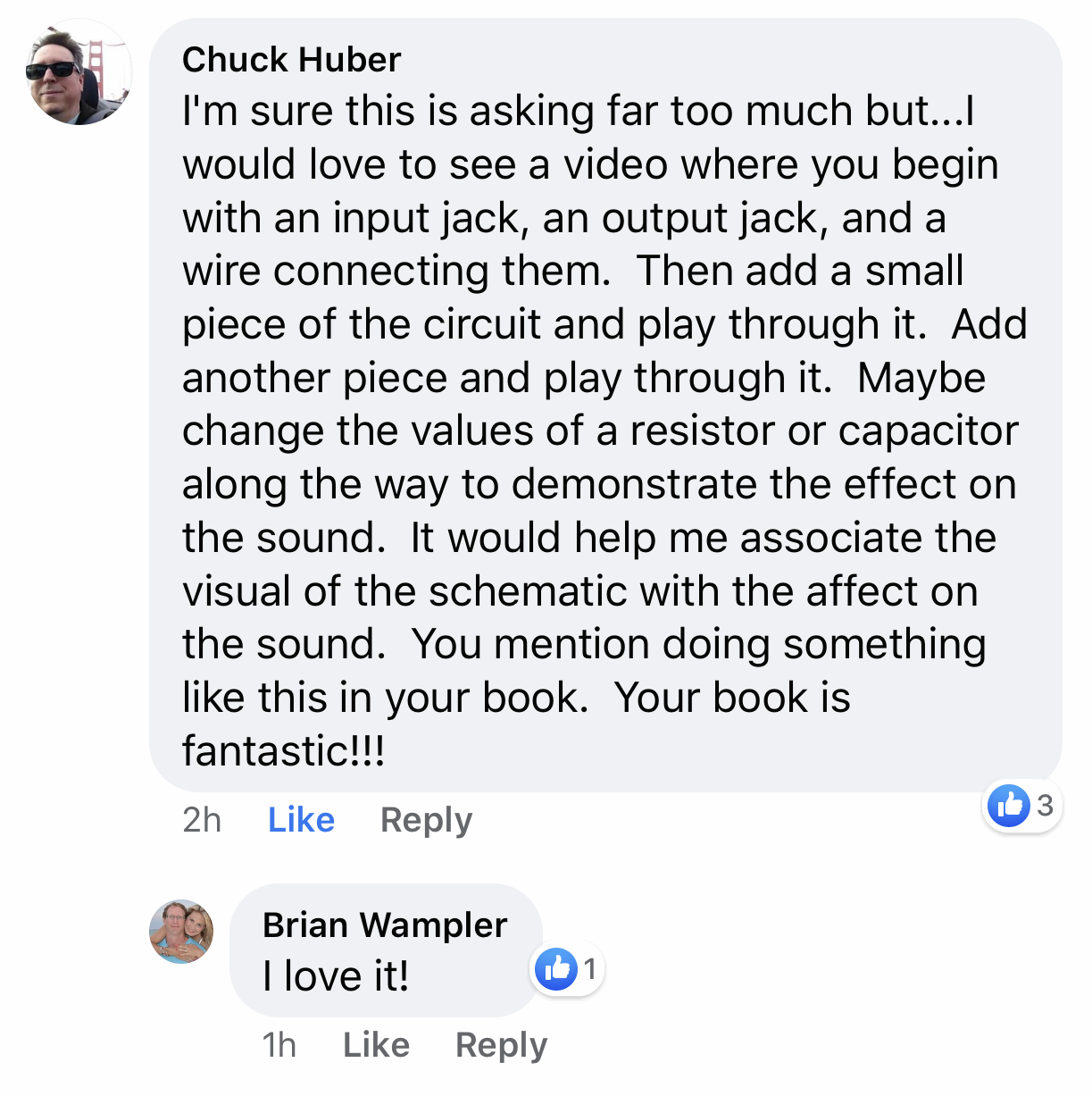
I always love the idea of helping us guitar tone enthusiasts understand roughly what’s going on with guitar pedal circuitry. Its a chance for me to get nerdy with a circuit, and it’s also fun to dispel some common myths too 😉 Win – Win.
So, let’s dive in and learn a bit about what goes into creating a very simple overdrive pedal circuit…
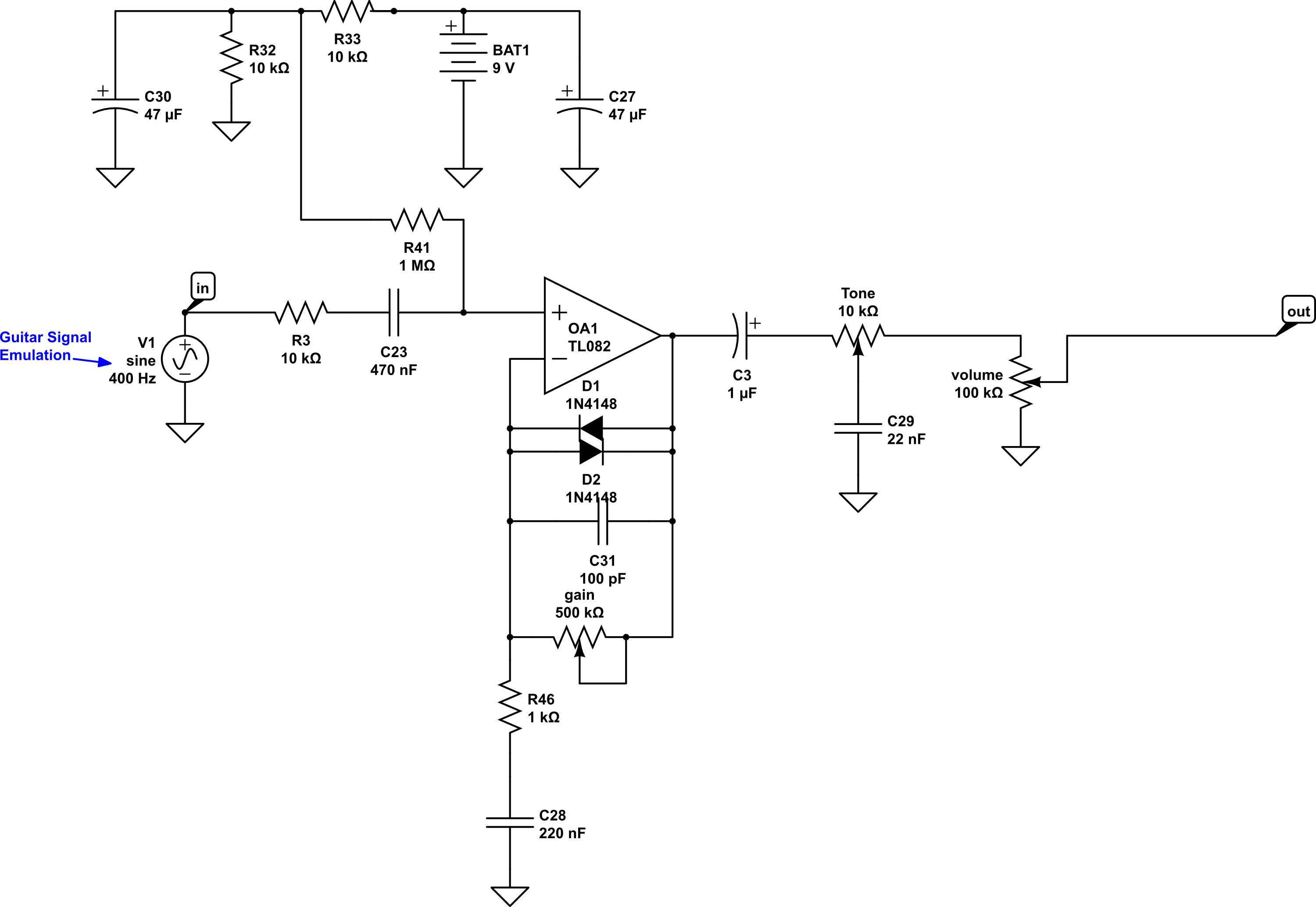
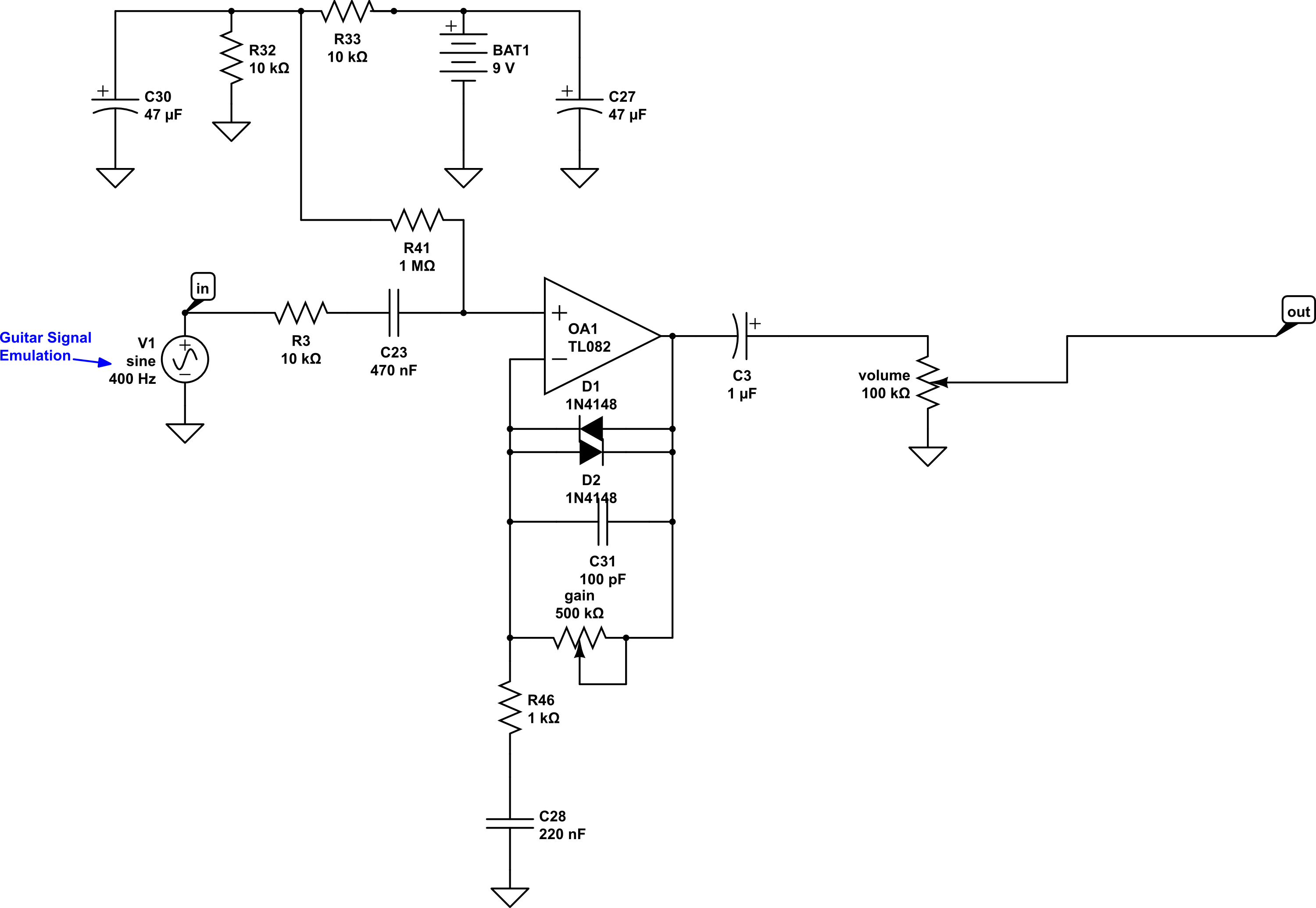
The circuit “starts” with the guitar signal – the V1 shown above this indicates it is a simple audio signal. It goes into the area marked “in”, above. The sound then travels through R3 and C23 before coming into the op amp, which is set up as “non-inverting” with soft clipping via diodes. Non-inverting op amps are a key feature of many circuits. From there it goes into a variable low pass filter, which we’ve called “Tone”, before going to the volume control. Now, assuming i havent already lost you and your eyes have not glazed over, let’s take it step by step.
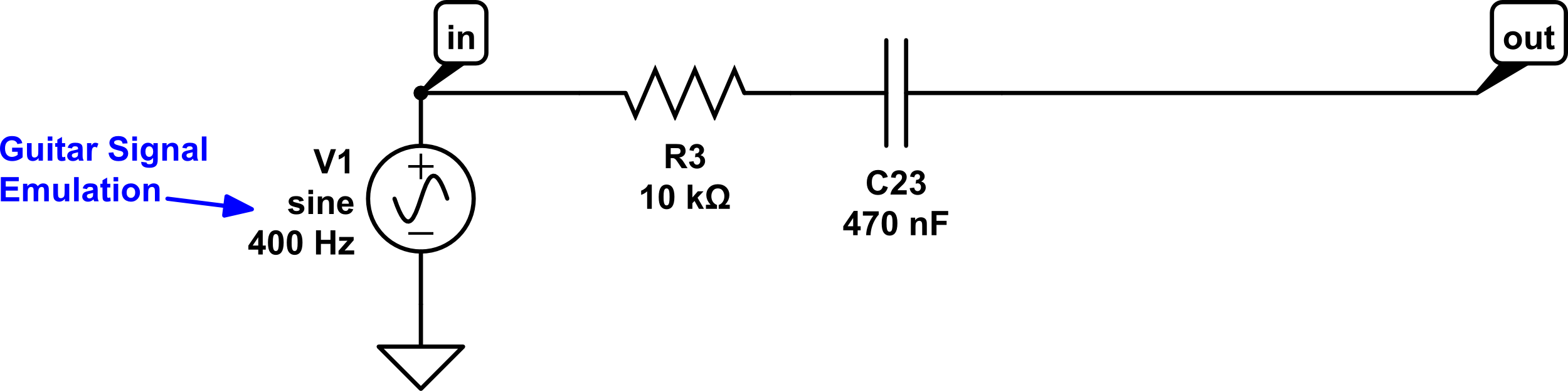
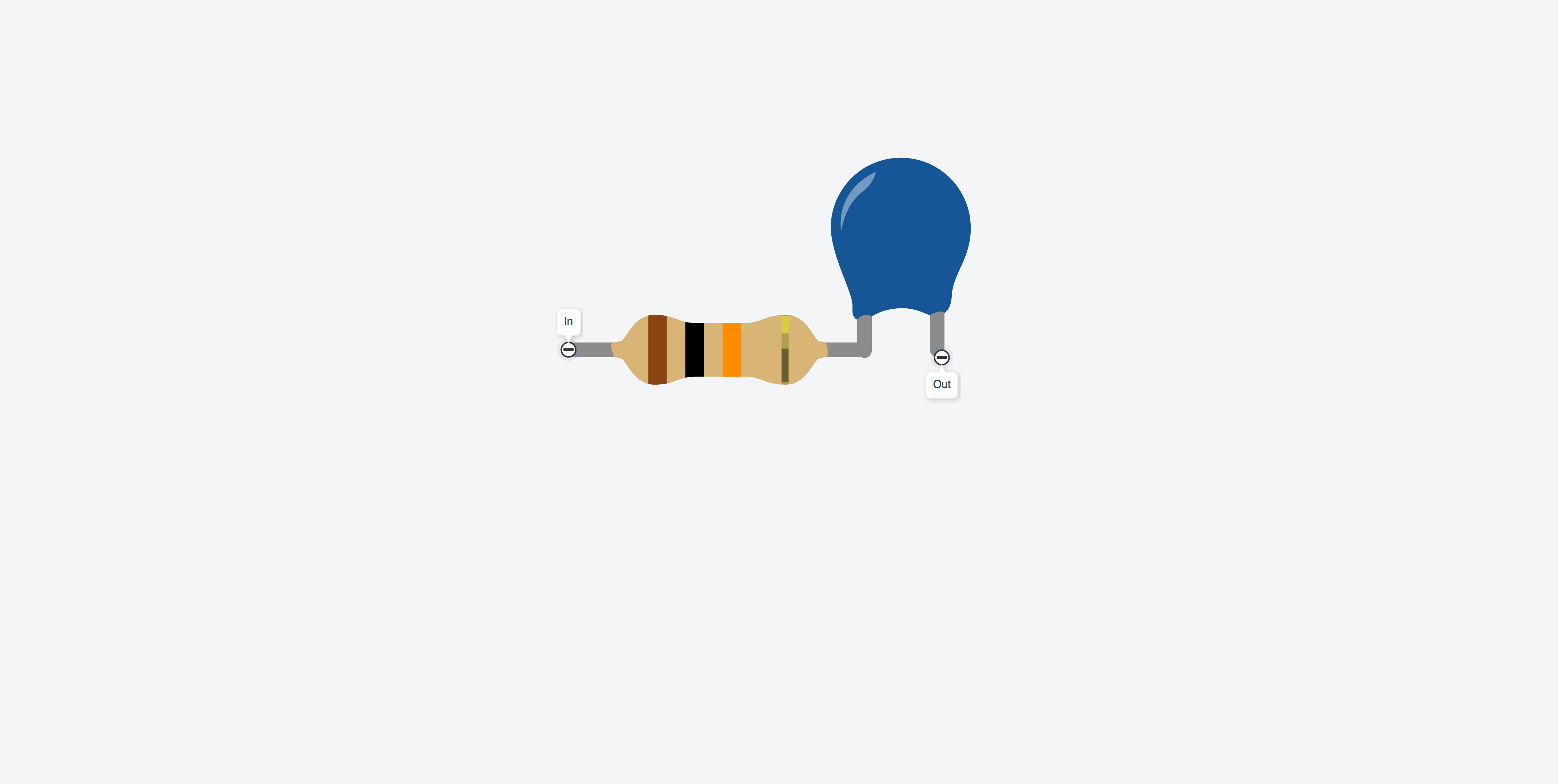
Up to this point our guitar signal is only going through R3 and C23, which looks like this:
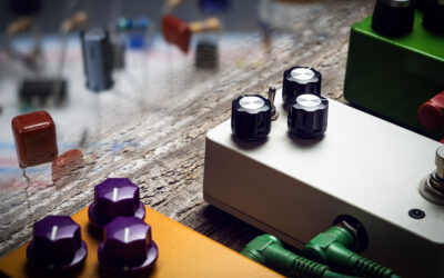
A look of the actual parts so far is pretty simple at this stage:
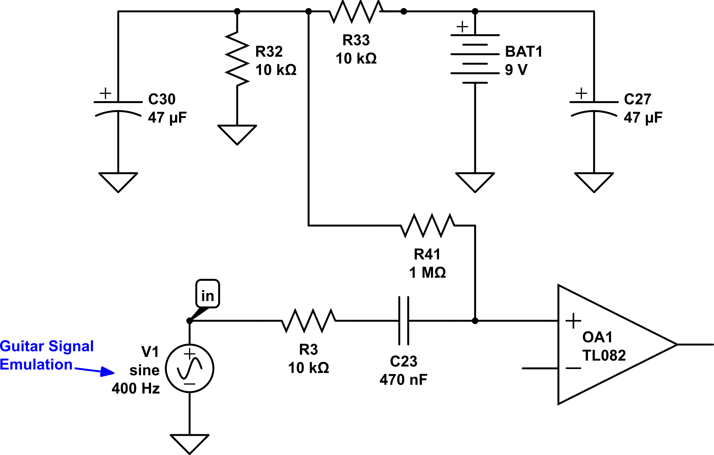
Let’s add some more circuitry. We are adding an op amp after it goes through C23. As i mentioned, op amps are common in many circuits, but what is an op amp? It’s short for Operation Amplifier (Logical so far 🙂 ), and in our case this is going to “boost” the sound up enough for us to create some distortion or overdrive. This is going to require several parts to make it work correctly, and we’ll use an IC chip, or integrated circuit chip, in order to do this. Our Circuit now looks like this:
Looking at the parts now, things are starting to fill out a little:
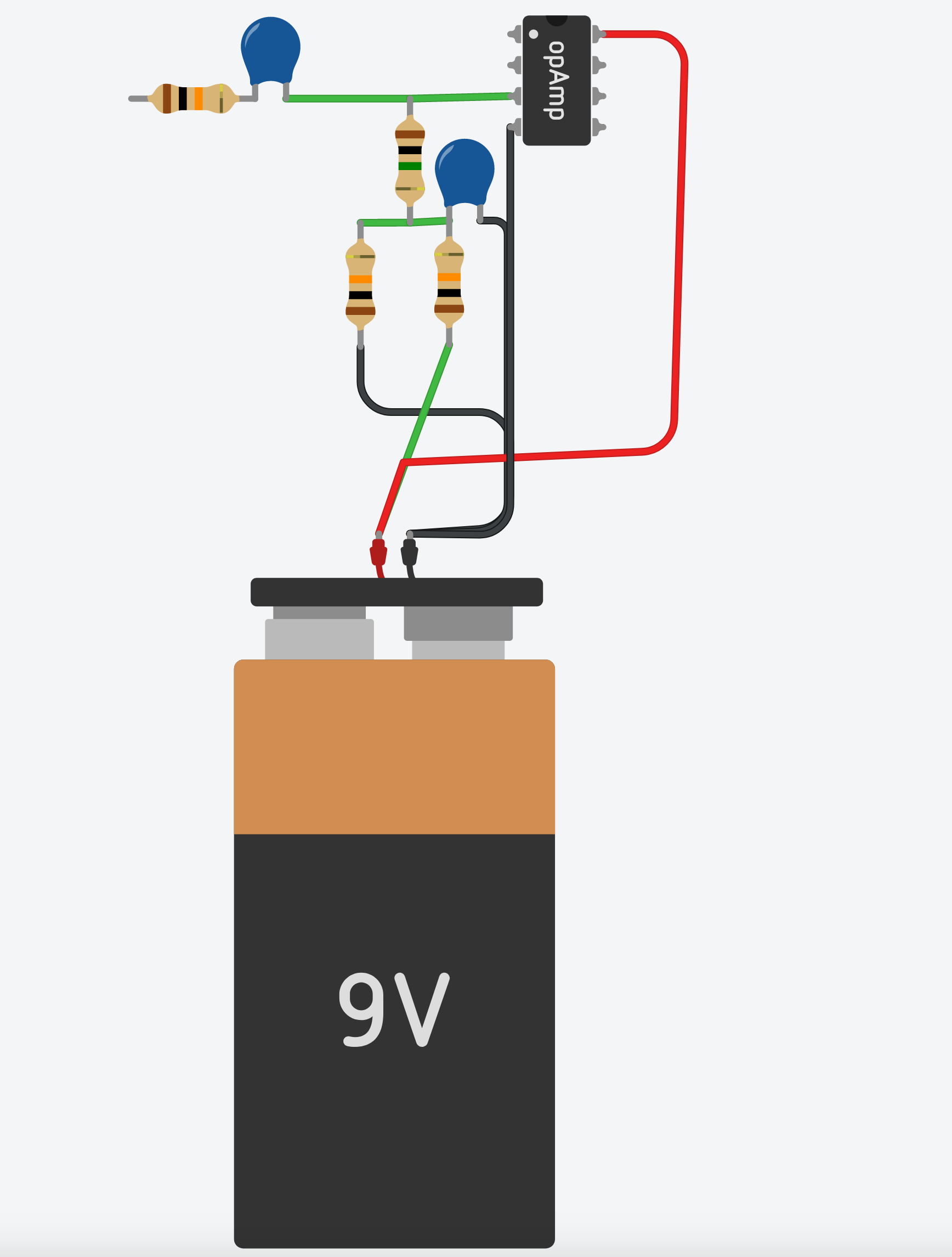
In order to make the op amp work properly, we are going to “bias” the op amp using R41, which connects to a simple power circuit. This power circuit originates from the battery, marked BAT1 above. You’ll notice that there is a + or positive symbol, and the other side has a triangle pointing down. This symbol indicates ground, which can be thought of as the opposite of positive voltage in this instance. A battery has two different connections on it… positive and ground. On this schematic and in many simple circuits like this, all grounds are connected together even though they show individual triangles.
It’s just one of those “it’s commonly understood” type of situations amongst circuit builders. Also, these schematics, like many others, “assume” that the viewer knows which two pins are going to connect to the power. I’m indicating “wires” containing power by red, while “wires” that are at ground are colored black on the diagrams that show the part. As ever, you will be attempting these modifications at your own risk – if you invert your power and blow something thats on you 😀
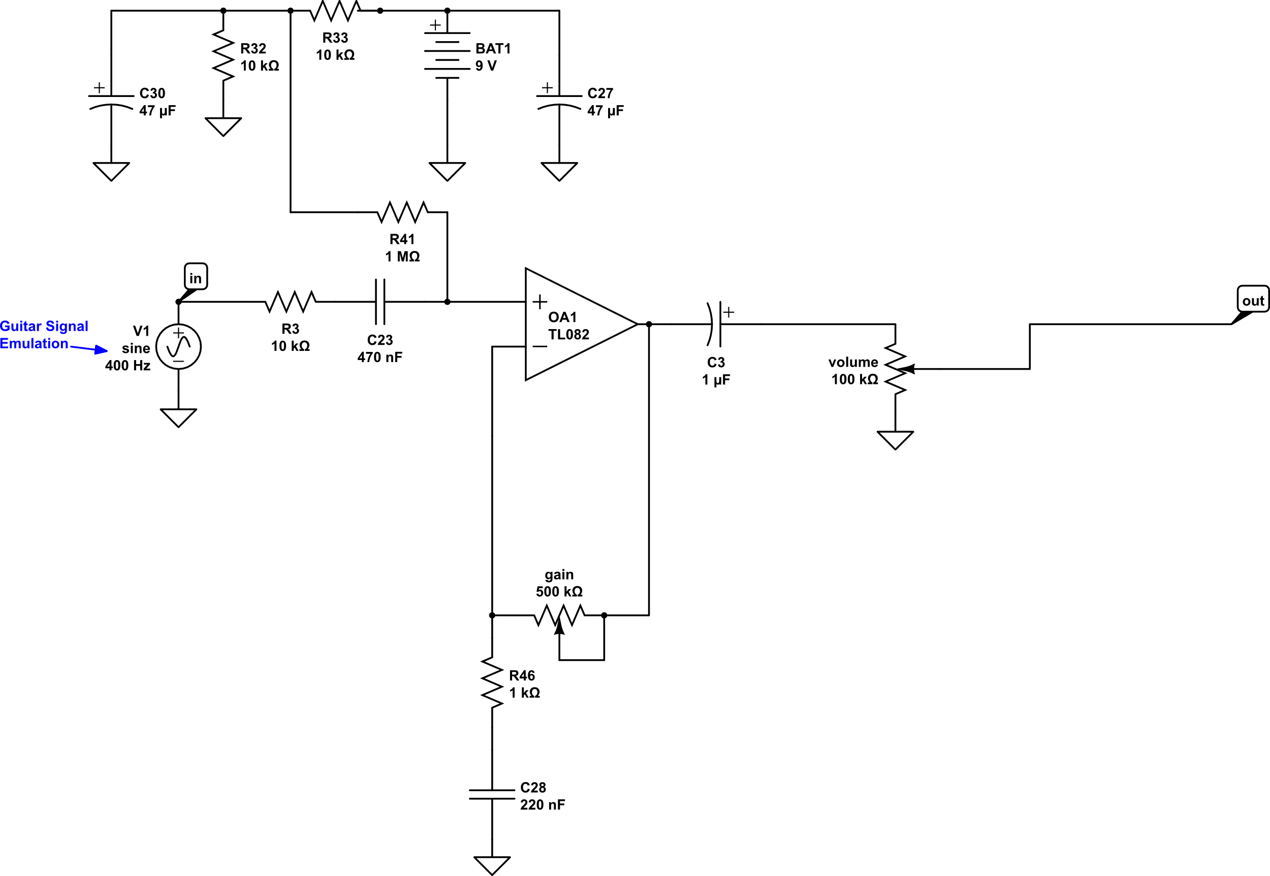
From here let’s add a gain circuit with the op amp. We’ll also add an output capacitor, C3, and a “variable voltage divider”, or what we commonly know as the Volume Control. How do we do all that? Like this:
And again, let’s take a look at what that looks like from the parts-view:
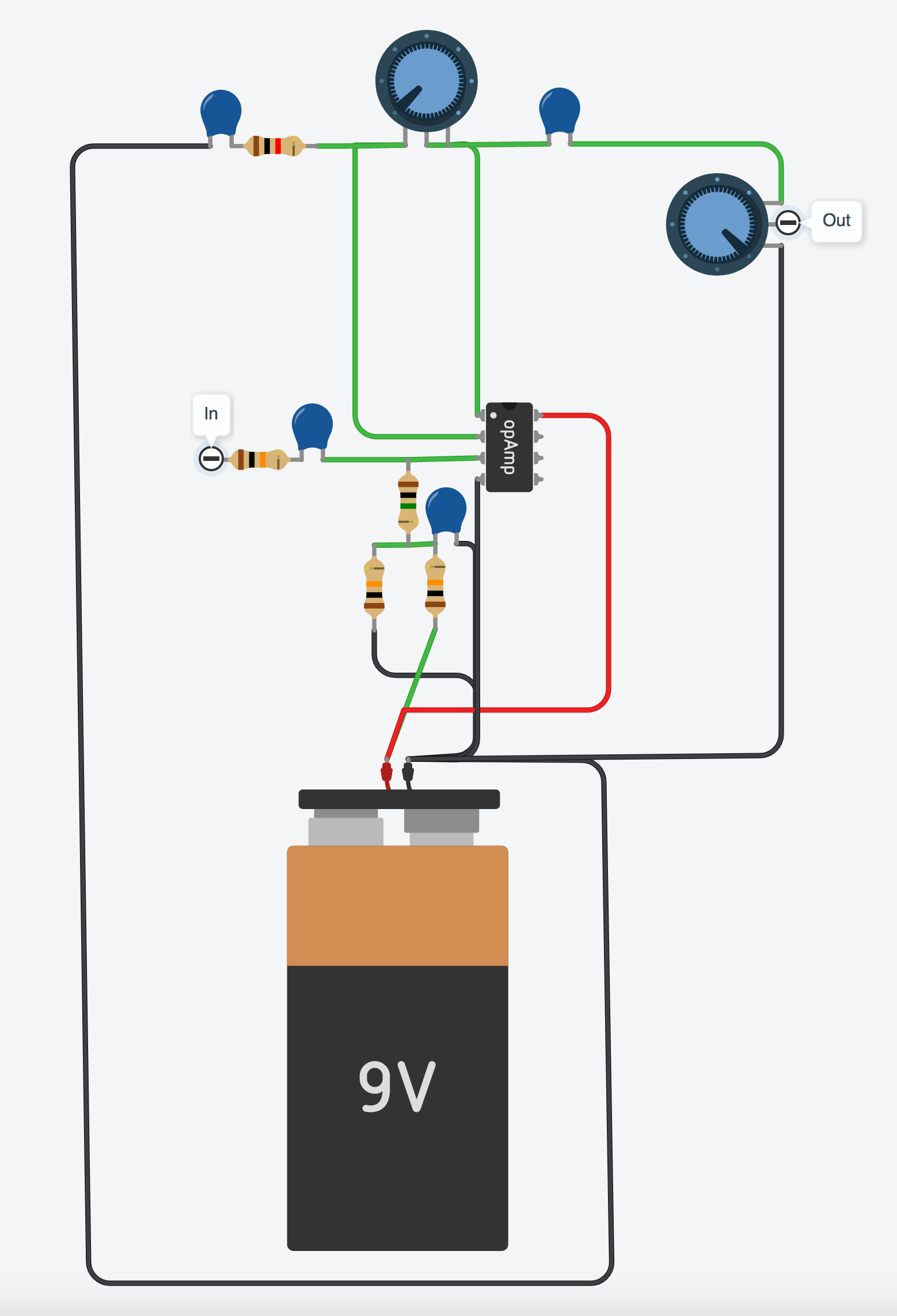
At this point we have a volume booster. If we turn the gain all the way down and turn the volume all the way up we basically have a buffer. That’s not exciting enough though, amiright?!
Let’s make this lil’ thing do some overdrive. One way to do that is just by connecting diodes between two of the pins of the IC chip. And, it’s good practice to put a small capacitor in parallel in parallel with the diodes and gain pot, as this helps sort of make the whole op amp circuit a little more stable, a little quieter, and controls some of the “fizz” inherent when clipping a signal.
Here’s our schematic:
Here’s the same thing but the parts view:
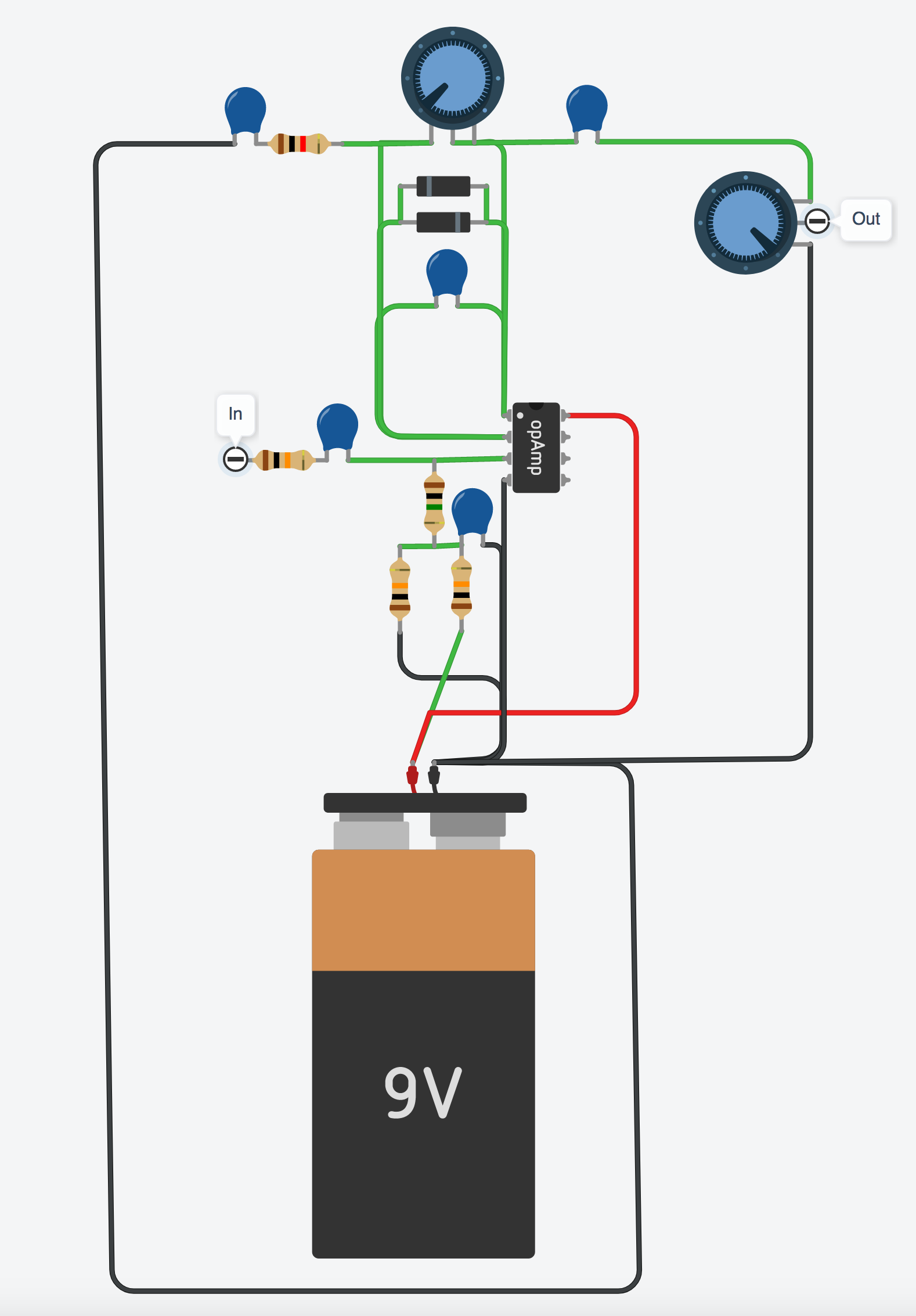
Now we have a basic overdrive pedal, but currently there is no tone control. Ya just gotta have a tone control. It helps to control the fizz and make sure the sound isn’t too bright for your tastes. Luckily adding one is easy peasy (now that is a phrase Ii don’t use often – the caffeine has kicked in!), let’s just put a simple tone control between the output capacitor, C3, and the Volume control. MMmmm. Coffee.
Schematic:
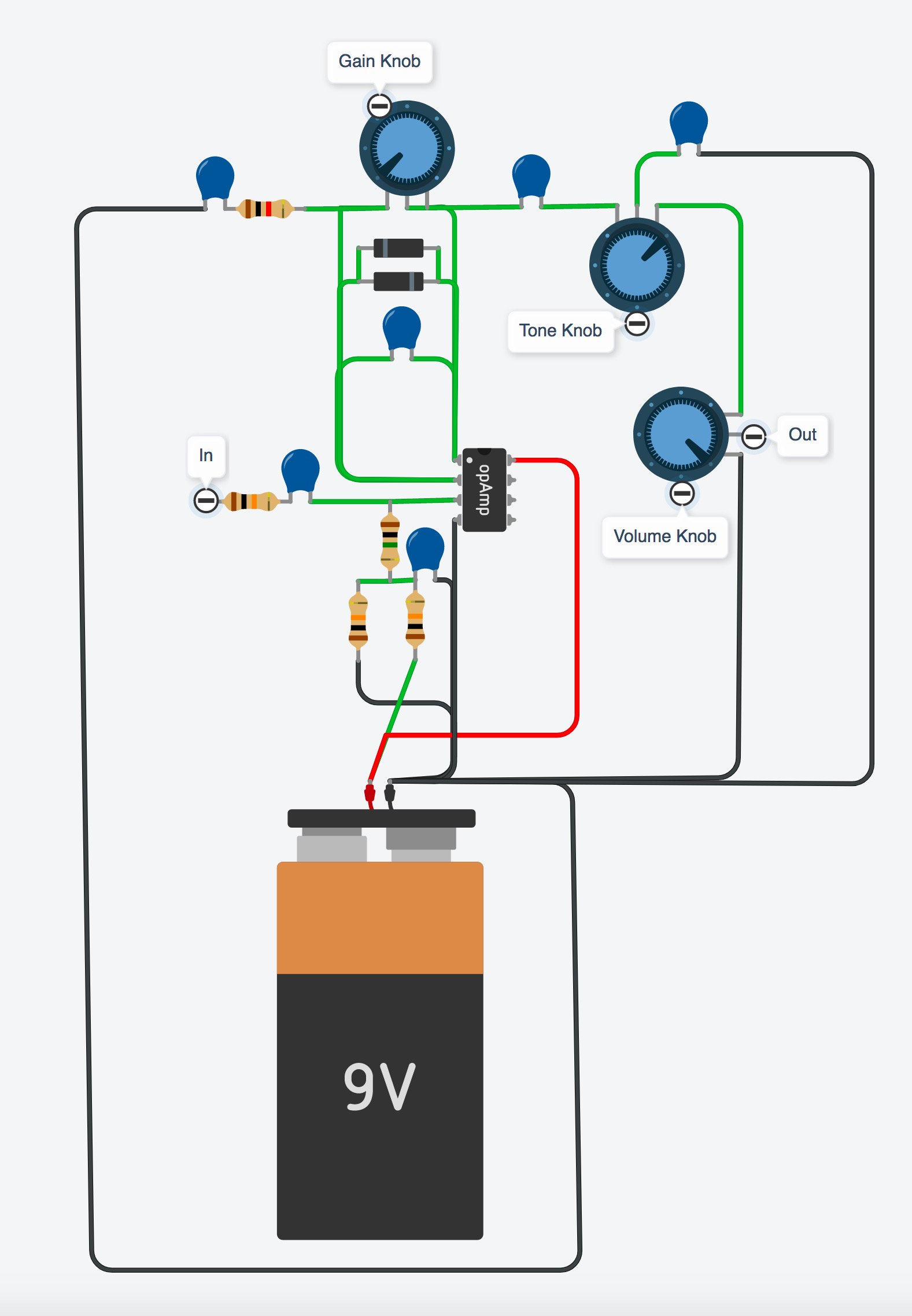
Boom! And there you have it – a completed, working overdrive circuit!
Keep in mind, this isn’t showing the bypass (IE on/off) switching, and there are ALWAYS many, many more ways to improve it or change it. If you want to check out how it sounds and go more in depth to what’s happening on a circuit level, make sure you check out my video here:
https://www.youtube.com/watch?v=F-WHBgIowmU
And if you want to learn how to design and build your own pedals check out my new courses where I’ll walk you step by step through how to do just this, no matter if you know nothing at all about electronics:
https://www.guitarpedalcourse.com
UPDATE: If you have enjoyed this article, be sure to check out my follow up here: How to design a basic distortion pedal circuit


This is really helpful, thanks! On a bit of a tangent, I was wondering if you have any tips on achieving negative voltage to provide to opamps when you’re just powering off of a DC +9v supply (like a battery)?
You’d need a completely different power section including special circuitry to achieve 9v+/9v-, but it’s outside of the scope of this blog … best bet is to hit up diystompboxes.com/forum
Is the part of the circuit which biases the opamp needed because the opamp is supplied with 0-9V instead of, say +/-4.5?
Guy, that is correct. If we ask the op amp to reproduce -2V, for example, we rely on the negative rail to the op amp to pull the signal down into the negative. Since this circuit uses ground for the negative supply of the op amp, the minimum voltage is 0V. (Technically, it’s more like 1-2V in real life.] The solution is to boost the whole mess up by 4.5V and then later on knock that 4.5V off with a capacitor.
What kind of capacitors did you used???
Where do we have to connect the ground of the guitar?
This shows using a signal generator. For the guitar you just need a phone jack, plug in like normal (in and out) and the tip (signal) goes into R3 (wire the tip of the jack to it) and the ground is chassis and connect to any ground point there. Same on the output.
How good is it to have someone openly share their expert knowledge and take the time to visually explain it.
Thanks
You’re very welcome Luke!
I dont see capacitor 30 on the wiring diagram it’s only in the schematics it’s confusing can you help plz
You might wanna check out Brian’s DIY site http://www.guitarpedalcourse.com for more detailed circuit / breadboarding stuffs 🙂
Sir where do we connect the ground part of the guitar jack please reply…
I think its connected to the ground of the output jack
Brian, you are a legend and it’s great that you continue to help out the community in the way that you make some things very logical . I recommend purchasing Brian’s book on Amazon if you want to learn all there is to know about the subject! I know I plan on buying mine next week Friday… Thanks again Brian!!!!
Thank you Jason – your kind words are appreciated!
WOW…!!!! First try, and it works. ITS ALIVE!!! ALIVE….
But speaking truly…ammmm…how can I say it…
…
….
….
I expected less from this circuit, but it not just sounds good, but also it works smoothly – I mean, gain and tone pot. make a full experience, but there is also a volume knob, which makes you realise, that you built in (with your hand) a amplifier which works wonderfully, especially with a weak audio system.
Thank you. You’ve not only made my happy ,but more importantly, made me achieve this eazy goal, that represents a comeback, from these years of stagnation.
I recommend this build for everyone, cuz it only took a day 2 build, and 2morow I’m going 2 make another.
Hi guy.
Doesn’t TL082 have 8 bases? So why is only a tripod seen in the schematic? And if only the tripod is used, what are those tripods? Why is the circuit description not accurate at all? For example, is the capacitor voltage of 47 microfarads not specified?
This may help Mehrzad: https://www.electronics-tutorials.ws/opamp/opamp_1.html
Yes, a TL082 is a dual op amp IC with 8 pins, but that’s how you draw an op amp schematically.
When I studied electronics, we did a unit on opamps. We did all the classroom work and then went to the lab to do the practical. When we were issued opamps I was so disappointed that they weren’t triangle shaped.
I see C27 in the circuit but it disappears in the graphic image, what happened to it?
You can do so by making a voltage divider- he actually does this if you look at the divider he has going to the 1 Meg resistor going to the non-inverting input of the op-amp- the inputs of the op-amp are a virtual ground and it gives the op-amp the feeling of having a +4.5 and -4.5 supply – the capacitors on the output help to align it as a pure AC output- at least that is how I learned to power op amps with a single supply
Hi Brian, I am building a tube amplifier and trying to work out a way to reinvert the output into the grid of a triode which the amplifier is globally grounded–I have dedicated DC off one half of a small signal coupling transformer. Is there a way to use this as a boosted input grid signal without inverting prior to the input grid of a triode? Or do I need to simply use a PNP FET boost? Thanks. Mike
Where is C27 in your diagram? C27 connects from the line with 9v input and a 10k from the bias and then to ground, I don’t see it?
I am wondering the same thing…. to add it in, or omit it… that is the question
Im trying to understand the gain knob connection, are the middle and right legs connected together or is the middle leg going down to the diodes and the right leg going to the capacitor? Separate connections? The two green lines are connected and its hard to understand if they are joined or not. Plz help. Tia
I am also wondering this. Can anyone who has successfully made this pedal help us with this? Thanks
The two legs are connected and the remaining one connects to pin 2 on the op-amp. Pots can be tricky, you also want to make sure the orientation is right so counter clockwise turning of the knob means less gain, clockwise means more. So I tend to figure it out that way, and looking down on the pot, the knob side label the pins from left to right as 1,2, and 3. Then I figure out which needs to go where. On the gain pot pin 1 goes to the op-amp pin 2 line. Pins 2, and 3 together on the op-amp pin 1 side. Think of it like a short cut…when the pot is all the way clockwise basically (look at the schematic) you are bypassing all of the 500k resistance of the pot, making effectively a jumper over it. When it is CCW the feedback must go through all 500k, and so is reduced. Making least gain. Hope this helps.
Hey Brian. What can I use in place of the TL082? I’ve got 5532s, 4558s, and LM358s and LM324s I believe.
I’ve used a 5532 and it works fine. Just check its datasheet to find the pinouts.
You can set up a voltage divider and bias the 4.5v as a ground giving a 9v battery a +4.5v and -4.5v
You can use a voltage divider and bias the mid point as your ground- it will essentially make a +4.5V and a -4.5v with your ground at 0v
Only one comment on the schematic. Others might disagree but ‘real engineers’ don’t use nano-farads (nF] — just microfarads (uF] or picofarads [pF]. If you actually try to order capacitors from a site like Digikey you won’t see nF parts listed — only uF and pF.
https://www.digikey.com/en/products/filter/mica-and-ptfe-capacitors/64?s=N4IgTCBcDaIMYEMAOC4EsAuB7ATgZxAF0BfIA
“Real Engineers “ more than likely wouldn’t waist their time pointing out such nuanced details that have no relevance outside of some alleged technical preference. Especially if they can understand the language, that is widely used in and outside of any accredited academic institution. It seems as if this Karen-esk commentary stems from a place of insecurity that needs to establish some arbitrary and honestly, sad sense of elitism to justify some large personal issues that might be a little neglected. But hey what do I know? I’m not a “real Engineer “
Ed, what you should learn from this is that real engineers do use nF. They also don’t. It varies by continent, country, company, and person. pF/nF/μF units are common in Europe. In the US I see both the pF/μF and pF/nF/μF conventions.
I’m an engineer in the US. My preference is pF/nF/μF. Digikey using pF/μF has never been an impediment. 😀
Yeah, sorry Ed… but this is entirely incorrect. I don’t even know an EE that can’t do the pf/nf/uf conversion in their head.
The reason that nano is avoided isn’t because of any particular preference among engineers- in fact they use nano all the time- the reason it’s not used in ordering and marking is because the n in nF looks an awful lot like the μ in μF and it wouldn’t be very good for someone to get a 1μF when they need a 1 nF ya know what I mean?
I am a 28 year electrical engineer and we DO use nanofarads (nF) in our designs, contrary to your statement. For a 30 nF cap, for example, order a 0.03 pF cap. Same thing.
Ummmm, you mean 0.03uF, not 0.03pF, right?
Nice work Brian. With the input frequency set at 400Hz, what is the rms voltage you start at or use for you initial design start?
I just measured my strats output at about 600 millivolts. Probably a good place to go.
Simple voltage divider network off the battery. (+)—20k—GND—20k—(-)
You can use a basic resistor divider, or go with something a tiny bit more sophisticated if you have a spare opamp: https://lh6.googleusercontent.com/proxy/SLd_u-mz2IXK5xBLgCjQfTHyk1YXIBoPmcLrfFfw-BDIulUawg2JJBYATb7wTnXD9N8DmYPpj3f3AbWHWKs3TiiDBmeBsitlNuwzCw
This is awesome stuff! One question, though, and maybe I missed something in the comments: am I reading the schematic correctly that the + leg of that output capacitor is facing forward? I would’ve assumed, possibly in error, that the flow would be + -> -.
It doesn’t really matter about the orientation because AC passes through either way. Convention is, however, that it is placed -+ on small signal inputs (guitar pedals, for example).
Hey there! I am very, very new to all of this, and I am extremely appreciative of the amazing resources you provide.
As I follow along here, step by Step, I think there might be a capacitor missing (starting with diagram #2]
-In the second schematic, I count 1 battery, 1 op Amp, 4 resistors, and 3 capacitors (labeled C30,C27,& C23).
However, I only see two blue capacitors in the corresponding parts-view diagram.
Again, I am brand new, so please forgive me if I’m overlooking something, but perhaps there Is indeed a capacitor missing from the parts view?
I am hesitant to continue past step 2 until I fully understand why the the two corresponding diagrams appear, to my inexperienced eye, to have a different number of components.
Thanks again,
-Johnny
P.S. I starting reading your DS-1 book last night, and am learning a ton!
Oops! Yes, there is supposed to be a capacitor in between the battery + and -, this would be C27
Thanks for this, I was also confused. I’m breadboarding this right now. So far I’ve boxed up a basic boost pedal and shelfed a fuzz pedal that I’m not sure what’s going on with. This will hopefully be my second pedal that makes it to my board! Thanks, I also enjoyed the video where you covered this same circuit.
Thanks for confirming this Brian! I’ve spent all weekend building this but wasn’t game enough to solder anything until I was sure whether that capacitor was supposed to be in there or not.. it’s been slow progress as this is my first build attempt, but really enjoying the challenge. Will complete the circuit now and hopefully it performs as well as others on here say it does. Kind regards, Steve from New Zealand
Hi Brian, long time listener, first time caller. I love your work. I came across your guide to modding pedals but I can’t seem to find a way to acquire it. Is there a way to buy it anymore?
Thanks! Here’s the link to the ones available currently: https://modyourownpedal.com/collections/books
Hi Brian,
Thanks so much for all your YouTube videos. I’ve learnt so much about circuits from them.
I’ve got an idea for circuit along the lines of a Boss OS2. Which I think is basically a Tube Screamer type soft clipping circuit running parallel with a DS1 hard clipping circuit in parallel. And then there’s a blend pot on the outputs.
I was going to use your simple overdrive circuit to breadboard to test something for fun. Could I change it to a Distortion by just moving the diodes into a hard clipping position? Or would you recommend making any changes to capacitor or resistor values to make it sound better as a Distortion?
It hasn’t got to sound amazing. I just want to test the blending part of the circuit.
Hey Brian, I’ve been tinkering with pedals with the help of your book and learning as I go and the one think I would like to do is learn how to add a blend/mix knob to a circuit like you did above (the breakdown of everything you did above helped tremendously!!!!!) I have a heavily modded DS1 that I have been working on and was wandering if you minded explaining or showing how I could add a blend/ mix knob to one so the wet and dry signals can be mixed together
Thanks!!!!
Hello.
Will this circuit be appropriate for a bass guitar?
What modifications could be made to make it more suitable for a bass?
Sorry, should C23 actually be 470pF? You mentioned a .47, and I don’t have any 474 caps, so I was hoping to use a 471.
Thanks for the great information, I found all the parts in my big box-of-electronics stuff.
I, I’m trying to understand how the “voltage” part is working here… If I got it right, the circuit you added with the op-amp is needed to have the guitar signal from 0 to 9V, with “silence” in the middle, at 4.5V.
But then isn’t the output weirdly offset for the next pedal? Why doesn’t it need to be moved down to 0 in the middle?
The opamp is biased to 4.5 volts. This is to center the signal around the DC offset of about 4.5 volts, which is necessary because we are powering the opamp with 9V and ground (0V). Since the (-) supply is 0V, the output of the opamp cannot go below 0, so we center the signal at 4.5 V by biasing the opamp, then use a capacitor before the output of the circuit to block this DC value. In other words, the capacitor removes the 4.5 V DC component of the signal, effectively recentering the signal at 0 before it moves into the input stage of the next circuit in the chain, where the whole process will happen again.
Think of it like this: voltage bias is the “starting point” of the signal.
The audio signal wave can only swing between the min and max voltage of the opamp before the opamp distorts, which in the above schematic would be between 0v and 9v.
So the signal comes in like a wave that goes up and down. The volume of the signal controls how big the wave is, i.e. how much it swings up and down.
In order to give the signal as much room as possible to swing before hitting the floor and ceiling of the opamp (this is called the rails), we want the signal’s starting point to be +4.5v. That way it has the most room available both up and down (it can swing 4.5v up and 4.5v down without hitting the rails).
That’s why you always want the voltage bias in the middle of the opamp rails.
The symbols for the electrolytic capacitors are not shown in the drawn version. So I’m a bit confused about why you placed them there on the wire map.
In theory using a ceramic instead of an electrolytic shouldn’t change anything, but I could be wrong
Everything is working as expected expect for the Noise. There is a lot of noise in the output which when played via an amp amplifies the noise as well making it much noisier. Any possible solution to remove/reduce the noise in the circuit?
Building circuits on a breadboard introduces a lot of noise that otherwise won’t necessarily be present in a circuit constructed on say, protoboard, or better yet an etched PCB.
Brian, is this basically the same circuit as used in your “Busting the myth of magical op-amps and diodes” video?
Hallo Brian, i find chip Toshiba TA7316AP 16pin version inside my old Radio Buzzer. Is the newiest version on used in Boss DS-1 op amp and cant working in bredbording ?
I so Happy with my new parts for bredbording.Trim pot cant work well in circuit for precision gain, tone… setting?
Thanks and great work, safe by the first. ????
HI, i´ve check de OPAMP datasheet, and it says that the power supply for it is about 18V, so how did you supply that voltage?
The opamp can be powered via a range of voltages, the upper limit of power that can be supplied to the TL082 is +/- 18V, but it can still be operated with 9V, as is done in this circuit.
I’m experienced with the TL072 and TL074 ICs and they work with 9V (and a bias) fine.
I think you can supply this op amp (TL082) with 9V, I think the 18V is the maximum Voltage you can supply. Increasing the the power supply simply increases the size of the output, which doesn’t really matter since it’s going to an amplifier.
If you wanted to, you could connect two 9V batteries in series to get 18V, but there’s honestly no need for that.
*Take my information and do your own research, I may be wrong*
This is amazing. You can learn all of this by reading a bunch about different band filters and source followers and reading explanations of circuit teardowns, but having it step by step like this is clever.
Thanks Brian for writing these and sharing your mods and designs throughout the years
Hi there,
I have a question regarding the taper type on the 3 potentiometers?
For the Volume, my guess be linear.
But are the Gain and Tone Pots Logarithmic?
Thanks for any help anyone can share
Have you figured this out?
volume is log (audio) taper
gain is linear
tone is linear
then why do industry pedals cost so much ?
why not just use an op amp and a boss EQ behind it ?
Im so much appeciated this tuturial. Even though i have a little knowledge in electronics. This tuturial will help us. Its easy to read and understand, unlike others hard to understand..thank you so much sirl
I’m having issues with the IC, wondering if you could relay what pins you are connecting to exactly? The pictorial diagram appears to not be connected to pin 7 although according to its datasheet that seems needed.
Appreciate your videos so much!
Hi Metal.
Where in the datasheet did you see that it is necessary to connect Pin 7? And to what? See, tl082 is a dual opamp or two opamps inside one package. Pins 1 to 3 are the first one and 5 to 7 the second one but Brian’s circuit uses one opamp only thus pins 5 to 7 are mit connected.
It is common practice to connect the pins of unused opamps to a voltage follower buffer with gain=1, meaning neither amplification, nor attenuation, though.
Regards,
Thomas.
I think
I pretty understand the fundament analogy
of how these stuff works
You are a very informative and caring musician. I watch your you tube shows here in Australia and always get some thing out of them. At present I’m building a overdrive unit using a (you guessed it a 4558 circuit). It has Tone, Vol, and gain. The out put at full gain is pretty hot. Is there a way to have about 30% of this gain run through one pot and switch and the remaining 30 to 100% gain run through a second pot and switch as a Boost. It would be easy to just parallel the 2 switch’s but thats not really what I’m after….Once again thanks for your products and infomation. Best regards Trevor. Australia.
And the 9v on pin 8? Pin 4 goes to GND?
Yes Guilherme, you are correct although I think it is 4.5v at pin 8, having been divided (biased} prior to reaching the IC.
Hello fig.
No, it is indeed 9v on pin 8. 4 and 8 are the power supply pins on most types of dual opamps.
The 4.5V you mentioned are bias voltage that belongs to the opamps input. This creates the “middle line” around which our sine audio wave swings. This is necessary because we don’t have a +/- supply here. In that case the bias would be 0v or ground and therefore no biasing would be needed.
Cheers,
Thomas.
.
Hey! This is just what I was looking for and I’m going to try building it! I purchased “How to Modify Guitar Pedals” and I’m finding it helpful. I’ve put together an amp kit and a pedal kit which is all well and good but I want to understand what does what more, without going into too much electrical engineering and the book does that well. The videos do that well too! Thanks!
This is AWESOME! I have your books and I have what might be a more advanced question. There are mods in the book for the boss ds-1 for synth fuzz, unfortunately the copy that I have just gives 3 examples of where to run the wire(s) for the mod and doesn’t go into detail on specifics about them. Can those mods be applied to the ts-9 circuit that is used here in this example?
Dear BRIAN, please describe you used favorite op amp TL082 reason purpose.
In last time i buy TL072CP, LM368N and LM358P.
Chips LM working in guitar distortion pedal circuit.
Digitech Hardwire “TS-2” Metal sounds for my best and any clone building cant by find on web.
Im so surprised, wenn i look red blinking two led in my Marshall Guvnor 2 Plus, Jackhammer and BluesBreaker 2000 all my collection pedals. ????
OMG amazing clipping work.
Your breadboarding video clipping germanium diodes sound’s best for my.
Thanks. ????????????
Hallo Brian, im engine technique in profession, but love stuff building pedals, tube amp, guitars…
Please you describe different between metaloxid film resistors and carbon resistors sound in circuit.
I not understend reason used in one example ceramic or polymer film caps.
Is sound clearity moustly different?
Thanks
They “sounds” the same. Their noise is minimal. Like 0.00001% of the whole signal and who cares of that in a distortion device? It’s an idiophile concept !
Can the TL082 be replaced by the KA358 (I found one in my electronic scrap)? Can the resistors be 1% metallic film or the normal 5%? Are capacitors made of film?
Can 1N4148 diodes be replaced by germanium diodes like 1N270, 1N34?
It’s a good project. congratulations!!!
I’m late to the party and pretty new to this, but shouldn’t C3 be facing the other direction in the schematic?
I have this question as well
I have a basic circuit using a TL082, with a 100k potentiometer to control the gain. I connected the output to my guitar amp. The op amp doesn’t distort (expected), so the signal tone is clean regardless of the potentiometer’s setting. The amplifier is overloading and distorting slightly and I don’t know why. I’m sure this is a common problem for beginners; any tips for things to check? Thanks
Trying removing C31 and see if the circuit works better now. I had to do that to make mine work.. was pretty clean with C31 installed and, voila, removing C31 made the circuit work properly.
Hello, everything sounds clear to me except two things:
1) I don’t like Batteries, so I would prefer 9V power supply.
Could I simply connect + and – at the same schematic’s battery leads?
2) Where is the switch?
I’d like to place a true bypass stomp switch on this Overdrive circuit.
Thanks.
Awesome job
Can someone make pdf with list of components, and maybe drawing with true baypass switch?
Would like to see a BOM for this
Why is the C23 capacitor usijg the value of 470nf going into the opamp? How is the 470nf value calculated? Thank you!
Hi. Great article.
I am just starting out and just wondering the function of some components.
In the power bit: C30, C27, R32,33,41.
Input: R3
Feedback: R46 and C28
Thanks
I have the same comment as Chris^^ why is C3 not facing the other direction? Thanks!
Ahh – Sorry – My bad – C3 is accidentally backwards, but normally I would use a non polarized film cap in that location
Hi Brian, I want to build an overdrive to put in a guitar, without any controls, just a push/pull pot to turn it on and off. What ideas do you have for something like that? Thanks, John
Hi John, I actually build and sell onboard dirt and boost circuits, I’d be happy to share some of them with you to build yourself. If you’re still interested contact me universalmind81@gmail.com
Just built this today and having some fun with it.
I’ve been experimenting with different diodes and noticed that sometimes there is a mix of clean signal coming through. Anyone else having this issue? Swapped with some LEDs and it’s not really an issue anymore.
Overall, really cool stuff. Gonna keep tinkering and figuring things out. Would like to get it a little tighter and brighter on the bottom end, but overall it’s sounding great.
Thanks, Brian. These articles and your breadboard videos are awesome.
Thanks Brian! I used this schema as the foundation for a multi selection dist/drive, where I added rotary switches to jump between different diode settings with a mix of Si and Ge and symmetrical and asymmetrical constellations. (1+1 OA74, 2+2 AA114/9(?), 2+2 1N60 and 1N60 in a 1+ [1..6] on a second rotary). I also set DPDTs to allow for Bass, Treble and Mid where C28 goes to ground (900nF, 220nF or 440nF) and similar at the Tone control (90, 22 and 44 nF).
I also kept a no-diode option as a boost. But as you said, it gets loud. How can that be “tamed”, so that it gets more “even”. It is ok to have the boost a little bit above, but right now it is too much vs the others.
Again thanks for the inspiration and I learned a whole lot from this!
Is the input impedance set by the 10k input resistor? You skip the input RC filter description and go right to the opamp… I’ve heard impedance is usually set going into opamps at 1Meg, same as most amplifiers. If so, is the bias resistor setting the impedance? Thanks for any help.
When you look at my finished breadboard, it looks like a mess. But it works. Thanks Brian.
I have built it and it worked right away! Thank you Brian!
You my friend, are an inspiration!
Ive built upon it. I slightly modified the bias resistor layout and added an active TMB tone stack!
I could use your help though.
Trying to get it to clean up a bit at low gain. Has a fizz at low gain.
Thank you again!
I have been having a lot of fun and learning a lot!!!
– Gator
Great diagrams! It worked when I tried it at home, with some tweaks, but it is great
what component is the opamp?
Hello,this is Liam from PCBWay.
Deeply impressed by your blog content which is means a lot to pedal makers. I’d like to sponsor your project by providing free PCB prototyping, only hope a slight promotion or a review about quality or service in return. Are you interested?
I see your voltage divider circuit uses resistors and capacitors to get 4.5V from a 9v source, I am trying to find a circuit like that that gives me 5V instead, but all I seem to run into online are ones built with resistors only, why do you use the capacitors? And how would I modify your circuit to produce 5V instead?
If you want to produce +- 5v you will need a supply voltage of 10V.
Hi Brian, thx for sharing.
Use the dual op amp’s second channel too! Instead output reaching volume pot, re-enter output into 2nd channel of the op amp therefore further amplify the signal and build another diode gain stack for the 2nd channel too with it’s own GAIN pot, then signal can go finally to output.
Hi! I have a couple questions!
1. What does the biasing do to the circuit? Does it add more headroom before the op amp clips?
2. Why is the capacitor on the output of the op amp polarized?
3. Do the capacitors (parallel with gain, on input, on GND of gain) help only to smooth the tone, or are they for decoupling?
As far as I understand (I’m a beginner):
1. biasing adds a DC voltage to the signal going into the op amp, which centres the signal around 4.5V instead of 0V.
2. Not sure
3. I think C28 helps bleed certain frequencies to ground, which affects the tone and maybe noise? I think C31 removes noise in the feedback loop. C23 removes any existing DC bias and I *think* it may also stop the voltage through R41 from going into the input signal, if polarised, but I’m not sure.
Hello!
What is the purpose of R41? Thanks a bunch for your time!
If C3 is polarised, which way round do you connect it to the breadboard? I know it’s to remove any pre-existing DC bias, but does it also stop the biasing voltage coming through R41 bleeding to ground or back into the input signal? Thanks
For anyone else reading this, Brian commented above that he accidentally got the polarity of C3 wrong in the schematic.
I’m trying to make this circuit but I don’t understand which on off switch to connect. How do I complete the circuit? Which element do I need to connect?
please help
You can simply connect a simple on/off switch to the battery connection (+). I also connected an LED across the switch so it lights up when the unit is powered and running.
Hi, I made this pedal and now put it on PCB, but when nothing is plugged in, it produces very loud tone, like a sine wave, and when guitar is plugged, it depends but when on bridge pickup it also produces that sound if I don’t play anything, but if I turn it down it stops.. it’s a little bit less on neck pickup and if the tone knob on the pedal is not turned all the way to bright.. I’m stuck pretty much now, please help, thanks 🙂
It sounds like you need to add some filtering.. I think the ‘loud tone’ you are referring to is hum. I get a similar response and added a HPF which helped a little. I am still tinkering with the design.
I built the above overdrive pedal circuit and it works but I get a good deal of hum. I designed a HPF to stick on the output (across the output of the volume pot to ground) but it pulls down a good deal of the output volume. It’s a 0.3 uF cap with a 10k ohm resistor. I designed the HPF to have a cut off above 60 Hz. I also tried a 5k ohm resistor value to also try it at 150 Hz. Has anyone else had the hum issue and successfully addressed it? If so, how.
Also, I had to remove the C21 (100 pF) cap that was across the diodes; with it in place, there was almost no distortion (overdrive). Without this cap, the overdrive circuit works. Not sure why this is the case; is the value of C21 in the schematic wrong. Besides the 1N4148 diodes, have you others tried other diodes to get varying clipping (distortion) sounds? I tried LEDs and noticed a difference.
Thanks.
I have grown to really appreciate amp and pedal builders. I have dabbled in amp mods unsuccessfully but want to get into pedals. Brian, thank you for extending your knowledge to the guitar community. I am attempting to jump out and build my first pedal. My question is on the power section, the components laid out: battery, C30, R32, R33, R41, & C27, is that pretty much standard for adding the power section to the main circuit?
Awesome tutorial, I just made my own yesterday, I also got most of the parts from a dead CRT tv!
Everything went smooth exctept the Tone control drove me a little nuts. I ended up wiring it differently from the schematic, in the schematic how is the “hot” signal getting to the volume pot?
From what I see it has 10k continously across it in the form of the tone pot. As a matter of fact my signal stopped at that tone pot.
I ended up attaching the hot out from the tone pot to the center wiper just before the tone CAP and it works as expected…
Had an issue with the tone control not doing anything. I had the out of C3 going to pin1 of the tone pot, pin2 going to ground via small capacitor, and pin3 going to volume pot. I can’t get it to do anything!
TL082 works, but why not use a rail-to-rail op-amp, such as the TI tlv247x series. They cost 2 bucks instead of 1/2 a buck. This opens the possibility of using a 3V coin cell (ubiquitous CR2032, for example)
Also, curiously as to why use R41 = 1 MOhm as a high impedance source for the rail splitter instead of a standard op-amp buffer. You’ll likely have 2 amps in the chip (TL082 comes standard with 2 amps, only 1 used in design). Cleaner living/cleaner design.
Op-amp gain maxes at 500x = 500k/1k. Seems kinda like overkill? At max gain, the input signal that causes saturation is 9V/500 = 90/5 mV = 18 mV. That’s a very small input. Of course, no one says we have to crank the gain all the way up, but that makes the dial touchy, no? Maybe that’s part of the desired clipping effect too?
Other curious design features, would love to hear about rationale for these:
1. R46 * C28 combo on op-amp makes frequency response roll off at ~ 730 Hz (= 1/(2*pi*1e3*220e-9) Hz). Why set the roll-off for mid-treble?
Thank you for sharing the design – looks like a fun one to build!
Im trying to understand the gain knob connection, are the middle and right legs connected together or is the middle leg going down to the diodes and the right leg going to the capacitor? Separate connections? The two green lines are connected and its hard to understand if they are joined or not. Plz help. Tia
I’ve been trying to comprehend this for years…
Math doesn’t do it for me… I’m visual… Thanks for the graphics…
I recall Moog saying he could “hear” how a circuit would sound before he built it…
This helps a little on the journey… 😉
You rock Brian! I’ve been getting my ass kicked by trying to make this nice and compact on strip prototyping board. One thing I keep running into.. the gain knob doesn’t seem to do much. If I take out the diodes, it pushes right to clipping the OP amp, as soon as I add the diodes, nothing. I’m just using random diodes with usual .6v silicone voltage drop, is that all I should need? I’m learning to hate strip boards. Maybe I should go back to the point to point ones..
I appreciate this page! I have returned to it many times over the years.
You have explained the different chunks of the circuit well and I understand what is what now, however I am curious:
How does one come to the specific values used for each component? I would love to see an article on that.
Hello, I’m a beginner. I found your website and the design worked quite well, but when I built it the second time, the audio gain is very low, and I hear a lot of hum, hiss and buzz, which is not good. What should I look for? If it matters, the bias voltage is 4.0V, and it’s connected after 470nF cap, on the third leg of LM358 (I ran out of the original op-amp at this time.)
Super basic question here. First step you say we put the signal through a 10k resistor and a 470nF cap. Ok. Why? How does this affect the sound? Why did you pick those values? Is it necessary or preference? What does it actually DO? Throughout the post, it would be helpful to know these types of things. Thank you for actually taking the time to explain and to interface with people, it seems a rarity these days and is very much appreciated 🙂
The 10k resistor helps with impedance, since guitars have a very high impedance, the 470nF cap (along with the 1Meg Resistor going to the power section) filters out a little bit of the low end creating a smooth high pass filter.
ps. If you search on youtube, you will find he made a video about this circuit, explaining what he did and making also little changes to let you listen to the various differences in values on almost every part of the circuit: https://www.youtube.com/watch?v=F-WHBgIowmU
There’s also another video by wampler explaining what every component of a typical overdrive do: https://www.youtube.com/watch?v=6SbwV8vx5LY&t=130s
look like a nice and easy one to build, thanks!! Gonna be trying it but with a 4558d since it’s what i have on hand, hopping it works, good thing sockets exist, at least i’ll be able to just swap the chip if it doesn’t!! XD Oh and by the way, dunno if it’s important, but just in case, according to the schematic your simplified drawing is missing one of the 47uf capacitor, the one on the right of the battery going between + and -!! :p
Hello, there’s a 1 Mohm resistor on the 4.5 volt voltage divider on the non inverting input. Can you please explain why is it there. The 4.5 volt bias is required for the ic to work correctly, but why the 1 Mohm resistor. Also, there seem to be missing the 9v power leads for the ic on the schematic, is that naturally assumed when drawing a circuit? Excuse me for asking rookie questions, since I’m a beginner. Also, I will be using ua741 op amp. I’m anxious to see will it work xD.
non everyones.. max preamp+normaly amp.he.he
I’ve been wanting to build an overdrive that’s mostly used for tightening up and boosting my old Randall century combo. But in addition to the three knob layout, I was wondering if I could add a mid level and mid frequency shift in the form of (are they called trim pots? The little internal adjustable pots) or regular ones it doesn’t matter. I know this isn’t the place to get the actual answer and how to do it but if y’all could point me in the direction of where I can figure out how to do it and what I might need I would be grateful. And thank you guys a lot for b ing awesome.
Hi,
Is R3 there for limiting noise or does it have other functions? In some schematics the signal goes directly via a capacitor and in to the opamp and in others there is this resistor… I like to understand the function of this capacitor.
Regards, Leif
Hi Brian, What clean preamp circuit to use for an ampless setup? I have an IR loader pedal and i want to pair it with a clean preamp pedal that is a good pedal platform. I am seeing the rog tonemender but some said it is a boost circuit and some said i will work as a preamp. Can you please give me some suggestions. Thanks.
I have a few questionss… I am a student working for the gratuation project and I am having some issues. I am using Circuit maker and have a AC voltage source at the beginning as it s stated but the Resistor and the source dont want to connect… also at the output, wouldnt there have to be another Voltage source since you plug a cable out of the pedal and into the amp?
What an excellent discussion on circuitry and construction. Thank you and definitely added a fan to the conversation.
Thanks
Glenn C
Capacitor 30 i don’t see in the wiring diagram only in the schematics
I maybe wrong but to me 47µF for C30 seems more than enough. 47nF or any other value would do the same job.
Circuit PCB — https://mega.nz/folder/OsQjnDoB#hYYpL1JaSec1G2zvhqXCdA
Check if there is anything wrong.
Has anyone tried putting the volume potentiometer on the input?
You can, but that just does the same that your guitar volume would do basically. It’ll limit gain more than anything else.
In this scheme, isn’t the audio coming out at full power from the Op-amp, which is only limited by the volume? Since the input volume wouldn’t control the power used in the Op-amp?
I’m not exactly sure what you mean by full power. It’s a 9v circuit, and it’s being clipped by diodes, so it’s not *that* powerful. It’s just basic audio stuff. My courses teach all this in detail and will help make it much clearer for you.
https://www.guitarpedalcourse.com/courses/complete-beginner-s-guide-how-to-design-your-own-guitar-pedal-circuits
and
https://www.guitarpedalcourse.com/courses/design-build-guitar-pedals
The tone control forms a voltage divider with the volume pot (which, itself is another voltage divider), so it’s not going to be uncontrollably loud… especially since the diodes are clipping the signal as it is.
I think I got it. Thank you.
Thanks for this! There are situations where I might be able to sit-in on a jam, and would like to not hassle with anything more than my guitar. As it turns out, I’ve a nice 1972 Les Paul, which I’ve already built some electronics into (compressor and noise gate), and it sound great just clean. But it would really be nice to have a tiny add-on overdrive/distortion option, without resorting to floor pedals. If I build your circuit here using SMD parts and small potentiometers, I’ll bet I can make it small enough to fit into a little 1″x1″ x 3″ box, and be able to just connect it to my guitar with a little patch cord, and then run it to whatever amplifier is available. I’ll try it out on a simple perfboard first of course, but unless it totally stinks I’m going to cut design and cut a small PC board for it, for an SMD design.
Oh! I just noticed that C3 should probably be oriented the other way, with it’s + side facing the Op Amp output. The OP amp output is going to be at + DC offset (about 4.5V), and it’s other side will ultimately be grounded to 0 V through the Volume and Tone pots.
Hello I’m working on the PCB for it, can someone tell me if its right?, Thanks!
Hello, I’m building the PCB, can anyone tell me if it looks good, Thanks!
– https://drive.google.com/drive/folders/110Ivvtkt278APgz8vD-PsO057ATUhGlL
Hey There,
Brian has a separate DIY community over on Facebook and at Guitarpedalcourse.com – the latter is a great place to share your designs for input 🙂
Thanks for this! Great info! J201 instead of a outputbuffer. Brilliant! More Amp feel. No hard-clipping in the feedbackloop but afterwArds. Now trying different IC’s and diodes. Great fun! Thanks again!