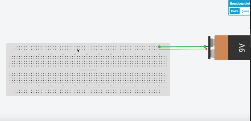
We get a lot of questions about breadboarding. It is an essential for any DIYer. Using software from 123d.circuits.io, we are able to give you the following tutorial on how to build a voltage amplifier circuit, or as many guitarists call it, a JFET booster. This is a basic breadboard layout. The battery, of course, represents your power supply, but any power supply will work.
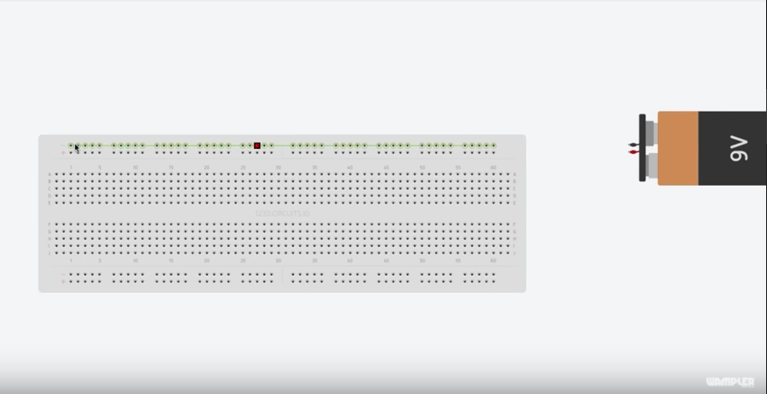
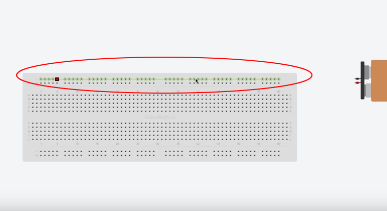
The top and bottom two rows are all connected horizontally.
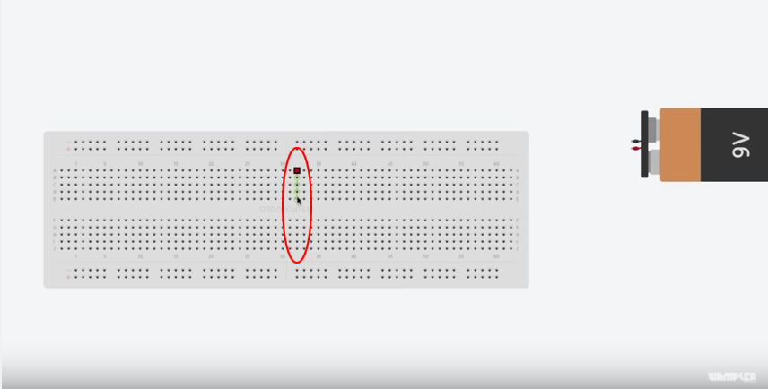
In the middle section, the holes are all connected vertically. This is important to remember, as this is key to how our signal will flow.
First thing we will do is run power into the board. We accomplish this by running a wire from the positive lead on the battery snap to one of the top rows. It can be any hole in that line, we just chose the closest. That entire row is now 9 volts power. And you do the same with the negative feed to the other row. That entire row becomes our ground.
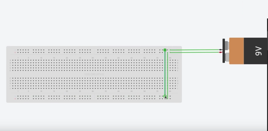
If you are building a circuit using op amps, you will want to run power to both sides of the board. This is done by using a jumper wire from the positive row and the ground to the bottom two rows.
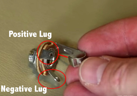
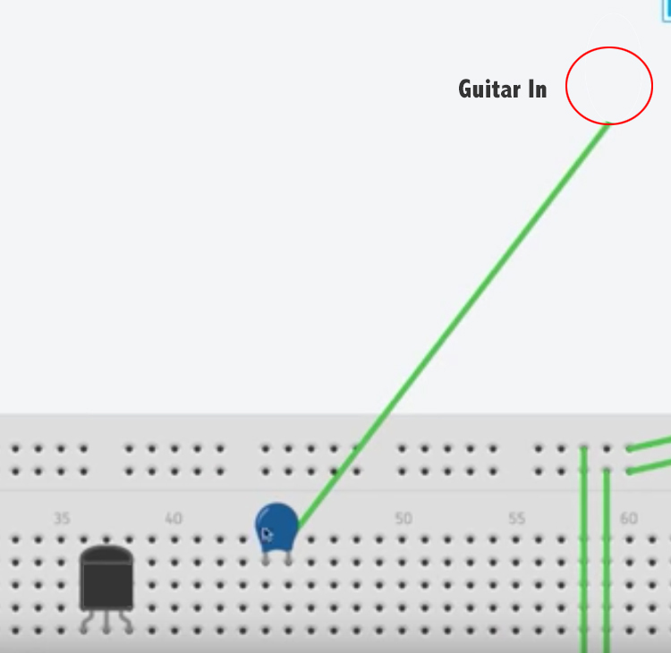
We are going to need an input and an output jack. Heat up that soldering gun. You will need to solder wire to the lugs on the jack. Notice how the negative lug is connected to the ring? This is where you will connect ground. The positive lug, which is connected to the tip, carries your signal into the signal chain.
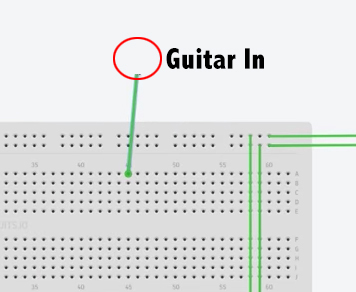
We will now run a wire from the positive lug to one of our columns in the middle section. You would then run a wire from the negative lug to ground.
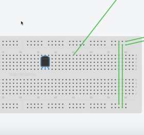
Now that we have the basics in place, we want to start this circuit out with a J201 JFET transistor. Notice how the three legs fit in three different rows.
Next we will need to add a .022 capacitor to the input.
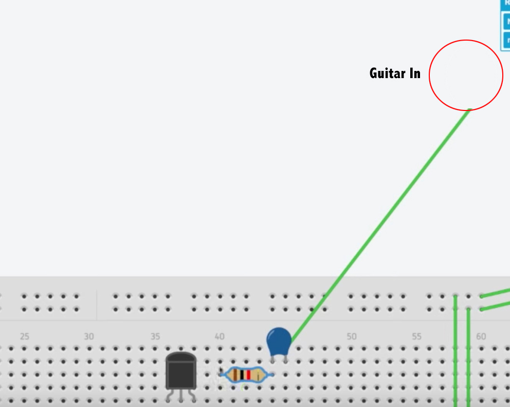
Next we will place a 1k resistor in parallel, in the same row, with the capacitor.
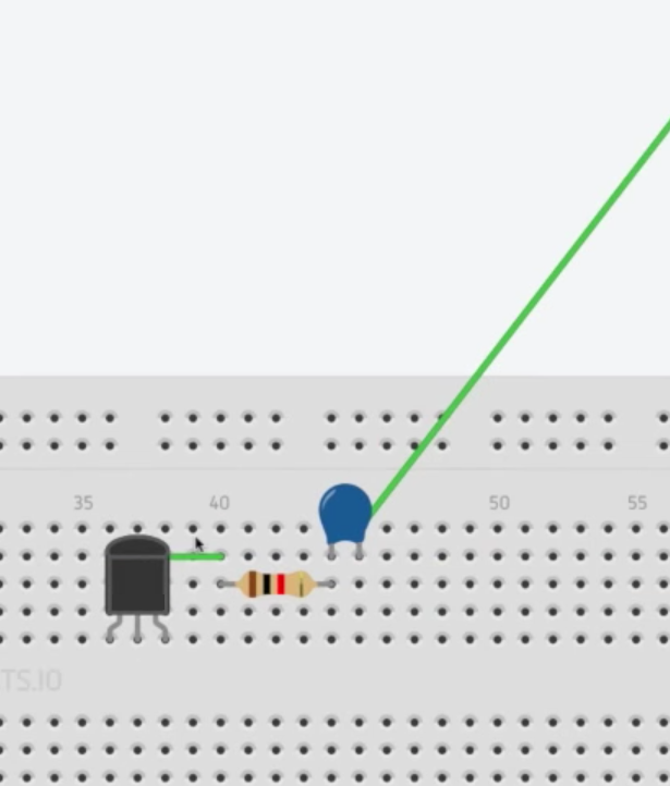
Now we want to run a jumper wire to the first leg of the JFET.
The middle pin of the JFET can be given many different values dependent on what frequency response you want or how much gain you desire from the circuit. You can use any size resistor, however we will use a 1k resistor for this demo. We need to attach one end of the resistor to ground and the other to a hole in the middle section. We will then run a jumper to the middle leg of the transistor.
Now we need to run power to the JFET. We do this by attaching it to out 9v line and then to a hole in the middle. Again we need to use a jumper wire to get to the third leg of the JFET.
This is a little tricky here. As this resistor value will be dependent on what is needed to get a 4.5 reading on a voltage meter.
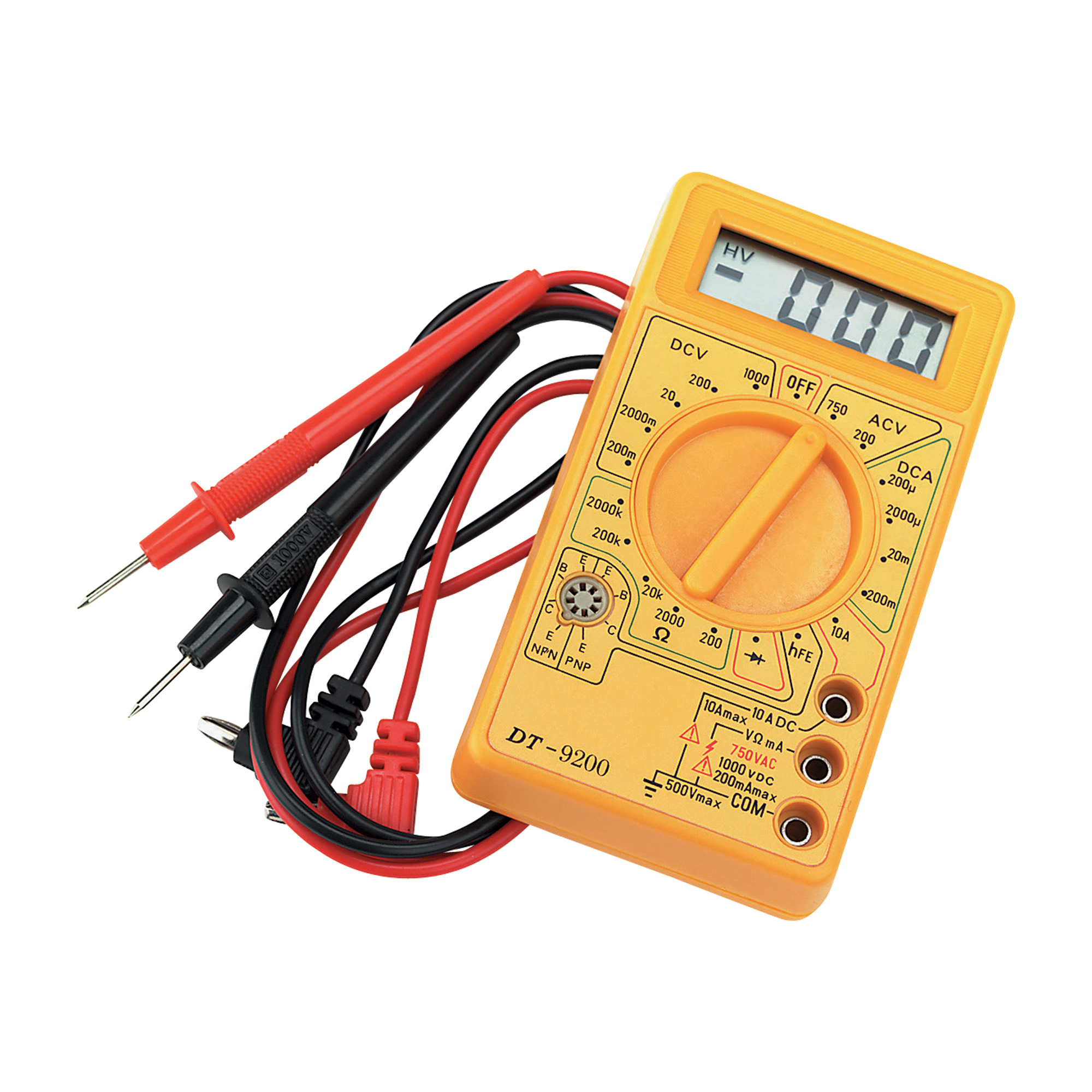
To check your voltage, you will need to attach the black probe to ground, and the red probe to the powered pin of the JFET. Then trade in resistors until you get a reading of 4.5 minimum.
It does not need to be 4.5 exactly, but I don’t like to go below that. Generally 4.5-5 volt is where you would like to be.
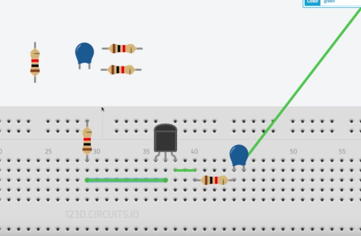
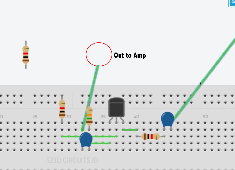
Okay, so the transistor has power and is working, but we need sound. Now we will add a capacitor where the power is coming in at the JFET. So we will connect it with the jumper wire that is going to the third pin on the transistor.
The other leg of the capacitor is where the sound will be coming out to your output jack. (Remember, when connecting your jacks to hook your negative to ground)
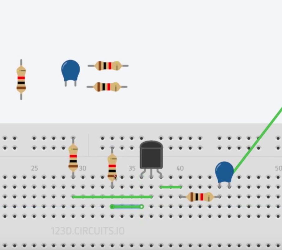
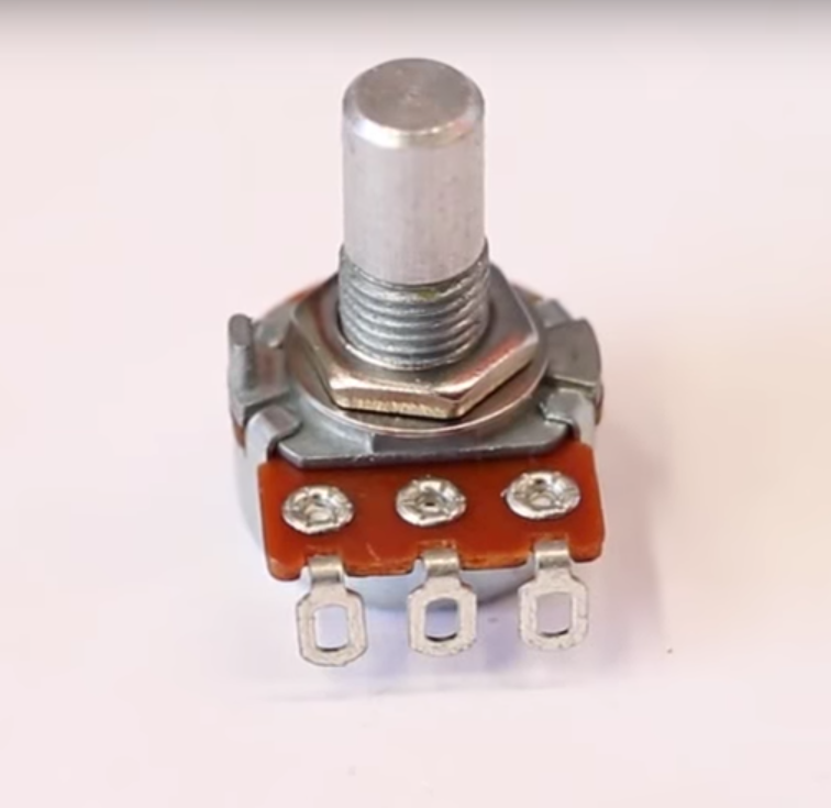
Warning: When you connect this breadboard to your amp it is going to be very loud compared to your usual guitar signal. This is because we have not added a volume pot yet. So let’s add a potentiometer. There are two types, wired and plug-in. For this demo we will use a wired type. We will be using a 500k for this circuit.
We will connect the third lug to the output of the capacitor. The first lug will go to ground and the second lug will go to a random hole in the board and then out to our output jack.
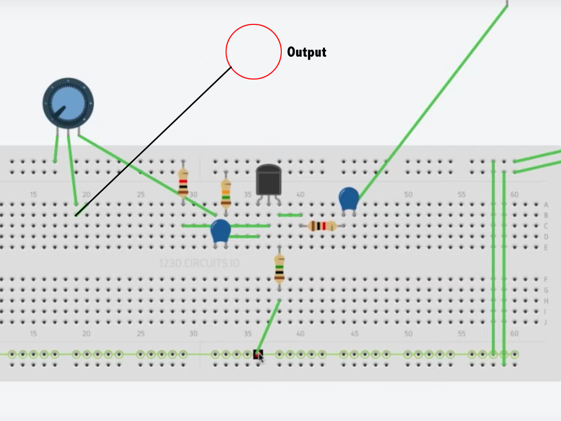
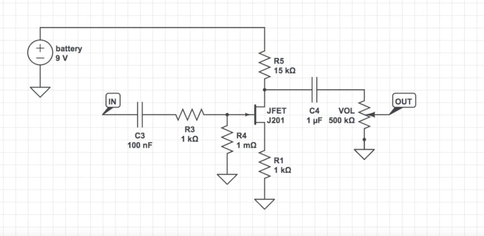
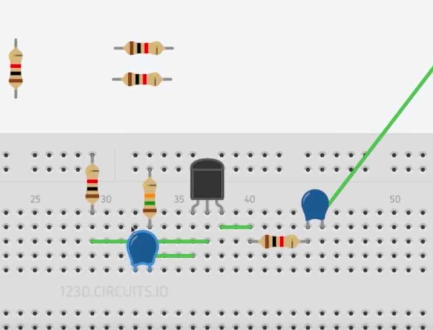
You may notice an added resistor in the diagram there. Very observant grasshopper. That is a 1 meg resistor that we forgot to add. It is attached to the first leg of the transistor, and then jumpered to ground. Our bad. So if we were to translate this to a schematic it would look like this.
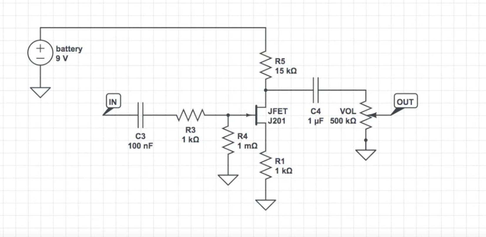
As you can see, it would run input to capacitor to resistor to ground to JFET to ground. R5 is going to change in value as you bias it to reach 4.5 volts, then the signal continues to our capacitor (c4) to our volume pot to negative to our output. And so we just breadboarded a JFET booster. Well done!! 🙂


Looks like the JFET is in a different row in some pictures. Are the later ones correct?
Shouldn’t matter…it’s still plugged into the same columns.
They just moved it so you could see the circuit better. Everything else stays the same since the holes going up and down are all connected.
Hallo DYI peoples, have problem with JFET 201J zero stock in eshops. PLEASE, recomendent equivalent datasheet spec.
THANK’S
This was an awesome moral booster project for a newbee.
Cheers
Hi Brian, thanks for this breadboard lesson. If I wanted to make it more of an overdrive then a boost what would I need to add or subtract in the circuit?
I appreciate you might not want to reply, that’s fine. I’ve made a fuzz circuit but would like to try an OD circuit but cant seem to make anything worthwhile on my board.
Thanks for the constant inspiration and lessons,
Gary.
Hi gary, you can add 2 1n4148 diodes to behind the 1uF capacitor. 1 diode will have anode up and cathode to ground, and the other will have cathode up anode to ground. You can also use 1n4001 or 1n4007 or even LEDs. You can mix and match any group of diodes. Hope i helped
This is explained in the youtube video link in the blog, but removing the diodes and limiting some gain will yield a boost circuit
The value of R4 can not be correct. 1 milli Ohm? Perhaps you mean 1 Mega Ohm ( capital ‘m’ )?
Yes, 1meg
Hi Brian, I tried making this today on my Brian inspired prototype board however when it came to biasing the transistor I got it close to 4.5v and from there the voltage would slowly drop on the meter. Do you have any idea why this would happen or whether this is normal? I also seemed to get different readings from wobbling components in the breadboard such as caps and resistors is this common with breadboard or do you think my breadboard is poor quality? One last thing are all the values for components in the diagram correct I remember at the start of the corresponding youtube video you said the input cap was a .022 but in the diagram it is a 100nf? Is 100nf the same as a .022 cap or did you make some alterations? Hope this finds you well and makes some sense and even better hope I get a response. Cheers,
Next we will place a 1k resistor in parallel, in the same row, with the capacitor.
In Series, right? (Not parallel?)
Hey Brian, This is a more general question, but I am starting out with breadboarding, is there a good instructional video f using any Multimeter? They are all a little different and it’s a bit confusing. The videos I have found kinda suck and aren’t tailored to tone circuit benders
Brian! Would you always go for 4,5volts even if the voltage you get from your power supply is 9,6volts? Or is should I view that as within the 4,5-5v ratio?
What is the standard approach for wampler pedals?